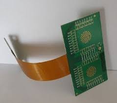
Components Arranged on a Flexible Printed Circuit Board
Modern electronics are becoming increasingly compact and more advanced. This is due to a combination of factors such as shrinking component sizes, more complex circuits, and shorter product lifecycles. As such, it is important for manufacturers to integrate their circuits into a finished product that will remain lightweight and durable enough to withstand vibration and other environmental challenges. This is where flexible printed circuit boards come in. They offer significant design freedom and can make it possible to combine surface-mounted components with plated through-hole technology.
PCBs that are not designed properly can end up with issues such as high-stress areas. These are areas where the stress from flexing can cause breakage and damage to copper circuits, and they must be avoided. In order to avoid these issues, designers must carefully plan out their designs for a flexible printed circuit board. This includes floor planning, which is the process of dividing the board into functional partitions for components. For example, digital, analog, RF and power areas will need to be located away from each other in order to avoid noise interference.
It is also important to consider thermal dissipation when laying out a flex circuit design. Hot running components such as processors should be placed towards the center of the board to allow them to disperse their heat more effectively. It is also crucial to consider the placement of individual power supplies and other devices that generate a lot of heat. Lastly, be sure to leave room in the design for heat sinks and other thermal dissipation tactics.
How Are Components Arranged on a Flexible Printed Circuit Board?
The most common conductive material used in flexible circuits is copper foil, and it serves as the basis for almost all etching processes. It is a relatively low-cost and versatile material, and it provides excellent conductivity. It is also a good choice for flexible circuits because it offers a balance between flexibility and strength, and it can be etched into a wide range of patterns.
Another important consideration when designing a flexible circuit is to select the appropriate thickness of copper. Thicker foils are more resistant to bending, while thinner ones will have a much more difficult time with it. Thicker foils can also be cut to a smaller size, which can help with reducing the overall thickness of a flex circuit.
Flex circuits come in different flex classes, which is determined by the level of inspection and testing that will be performed on the finished product. This also determines the minimum acceptable bend radius for a flex circuit. It is important to understand these differences in flex classification, as they will affect the type of flexible circuit that can be created for a given application.
Single-sided flex circuits are the most basic and affordable options on the market, while double-sided flex circuits offer increased power handling capabilities. Both types of flex circuits require careful layer stack planning to prevent stress-induced problems during the manufacturing process. In addition, they should be inspected during fabrication to ensure that all of the layers are connected correctly.